|
<< Click to Display Table of Contents > Analog A And Analog B |
  
|
|
<< Click to Display Table of Contents > Analog A And Analog B |
|
Analog A and Analog B are the outputs of the internal 8 bit D/A converters and provide signals in the range from 0..2.5 V (position 1), 0..5 V (position 2) or 0..10 V (position 3) with respect to GND. The supply for this circuit is generated on board from the +5 V main supply.
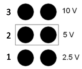
Figure 14: Analog output range selection
The output range can be selected by jumpers JP5 (Analog A) and JP6 (Analog B). The above example shows the settings for the +5 V range for both outputs (default).