|
<< Click to Display Table of Contents > Board And Connectors |
  
|
|
<< Click to Display Table of Contents > Board And Connectors |
|
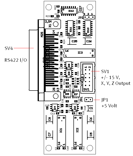
Figure 21: AEB-1 connectors
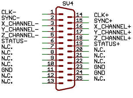
Figure 22: SV4 - 25-pin connector pin assignment
|
N.C. : Do not connect! |
|---|
The 16 bit analog outputs are provided as a differential signal for the X, Y and Z channels via the 10 pin connector SV1. For operation an external +/- 15 V supply must be connected. Each channel can be configured to either +/-5 V or +/- 10 V output range and can deliver 5 mA .
|
The negative signals are used for scan heads with differential inputs. When using a scan head without differential inputs the positive signals are used in respect to ground (pin 6 or 10 AGND). |
|---|
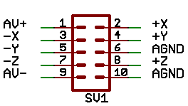
Figure 23: SV1 - 10-pin analog connector pin assignment
Pin |
Name |
Comments |
|---|---|---|
1 |
AV+ (+15 V) |
+15 V positive supply in respect to AGND, 200 mA max current. Appropriate fuse for circuit protection must be provided by the external circuit. |
2 |
+X |
Positive X channel, max. 5 mA current |
3 |
-X |
Negative X channel, max. 5 mA current |
4 |
+Y |
Positive Y channel, max. 5 mA current |
5 |
-Y |
Negative Y channel, max. 5 mA current |
6 |
AGND |
Analog Ground, Connected also to pin 10 of SV1 |
7 |
-Z |
Negative Z channel, max. 5 mA current |
8 |
+Z |
Positive Z channel, max. 5 mA current |
9 |
AV- (-15 V) |
-15 V negative supply in respect to AGND, 200 mA max current. Appropriate fuse for circuit protection must be provided by the external circuit. |
10 |
AGND |
Analog Ground, Connected also to pin 6 of SV1 |
Table 11: AEB-1 10-pin connector assignment

