|
<< Click to Display Table of Contents > USC-2/3 Specific Calibration MOTF |
  
|
|
<< Click to Display Table of Contents > USC-2/3 Specific Calibration MOTF |
|
Before starting with any Marking On The Fly application, the optic system needs to be well-calibrated in the static situation (no belt movement).
The flow chart in figure 359 shows an overview of the general steps of the MOTF software setup calibration. Please proceed with the steps below.
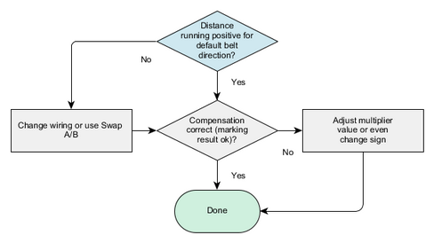
Figure 359: Flow Chart MOTF software setup
1.Check the proper alignment of the scanning field and the scanning direction?
•This can be tested e.g. with marking one line in the moving direction without moving the belt and marking a single point (with a mark loop count of -1) with the slowly moving belt on top of the last marking.
•If the alignment is not good, this can be solved by adjusting the hardware setup or within the correction file.
2.Mark without MOTF settings (without compensation) in SAMLight:
•Start the belt in the default direction with a slow movement. Mark ABC-circle.sjf. It is OK, if the marking result is not good because this marking is a reference to compare with a marking with MOTF compensation (see 360 1)).
3.Activate the MOTF compensation in SAMLight:
•Activate SAMLight → Settings → Optic → Advanced → Marking on the Fly by clicking on the checkbox 'Enable'. Then, please reopen the Advanced dialog.
•Enable Channel 0 for MOTF inputs on the 37 pin connector or enable Channel 1 for the MOTF inputs on the 40 pin extension connector (according to the electrical connection of the encoder).
•Select X-Channel or Y-Channel (or Rotation) according to the movement direction of the belt. Note: due to a flip in the optic settings the correct channel might be not obvious.
•Select the multiplier unit: counts/mm. The units m/min or mm/s are also available (for Simulation Mode with a reference of 100 kHz).
•As a starting value, set the multiplier to the value which can be calculated following the formula here.
•Click on Apply and on the store button in the Optic → Advanced dialog after any MOTF settings changes.
4.Start the belt with a slow movement in the default direction:
•Is the value of 'SAMLight → Settings → Optic → Advanced → Marking on the Fly → Distance' counting positive?
oIf not, change the wiring of the MOTF tracks (A and B) or use the checkbox "Swap A/B" in Settings → System → Optic → Advanced → MOTF.
oMake sure that when driving in the default direction, the distance counter will move in positive direction. Otherwise, the ScMotfOffset control object for example will not work properly.
•Move the MOTF belt for different defined distances. Is the distance value displayed in the software correctly?
oIf not, adjust the MOTF multiplier value.
5.Mark with MOTF settings (with compensation) in SAMLight:
•Start the belt in the default direction with the same slow movement as in 2. Mark a job like ABC-circle.sjf. Compare the marking result with the result in 2.
Is the marking result getting better with compensation or getting worse? This can be easily seen when looking at the gap of the circle. There are 3 different cases (see figure 360 2)).
oIf the result is getting worse (see figure 360 2)a)) - e.g. the start and end of the circle are farther apart, change the wiring of your encoder or change the direction of the compensation by changing the sign of the MOTF multiplier value. See table "USC-2 MOTF settings for different setups" for more details.
oIf the result is getting better (see figure 360 2)b)) - e.g. the start and end of the circle are coming closer, adjust the MOTF multiplier.
oIf you run into overcompensation (see figure 360 2)c)) - e.g. the start and end of the circle changed orientation in the direction of the movement, fine tune the MOTF multiplier.
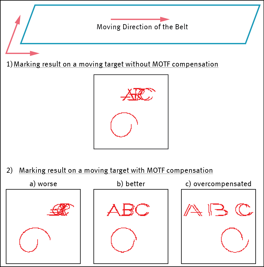
Figure 360: Different cases of MOTF compensation. For a moving belt to the left, an example of a marking result of ABC-circle.sjf without MOTF compensation is shown in a. When the MOTF compensation is activated in SAMLight, the marking result depends on the precise value of the MOTF multiplier. Three different marking results for three different MOTF multiplier values are shown in b.
6. Mark with MOTF settings a job containing 2 entities separated by a ScMotfOffset entity.
•Create a job containing 2 entities, e.g. two vertical lines and center both entities in x and y. Add a ScMotfOffset entity at the beginning and specify a certain distance, e.g. 10mm. Add a ScWaitForTrigger entity after the first line entity, see figure 361 a).
•Start the marking. Are both entities marked?
oIf you are just seeing the first entity, change the checkbox invert Offset in SAMLight. See table "USC-2 MOTF settings for different setups" for more details. "
•Is the distance between the entities as specified within the ScMotfOffset entity (see figure 361 b) for visualization)?
oIf not, it could be that the marking time of the first entity was too long for the offset. Try with a larger offset or faster marking speed or smaller entity. Alternatively, the initial external trigger was applied longer than the corresponding offset time. Another possibility is that the 2D calibration of the static setup or the MOTF multiplier is not yet optimal.
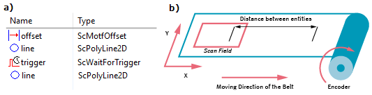
Figure 361: a) Example job containing 2 lines, ScMotfOffset and ScWaitForTrigger. b) Visualization of the marking of a) where the distance between the entities (lines) is defined by the value of the ScMotfOffset entity.
|
It can be helpful to activate the Error Warning Info for Out of field and Overflow MOTF offset. |
|---|
|
The amplitude of the encoder signals should be in the range of 2.5 V to 5.0 V. The signals should be as low-noisy as possible, since noise could be interpreted as additional pulses. Possibly, you can use a differential encoder and MOTF_CH1 (40-pin connector). |
|---|
