|
<< Click to Display Table of Contents > Wait for Input |
  
|
|
<< Click to Display Table of Contents > Wait for Input |
|
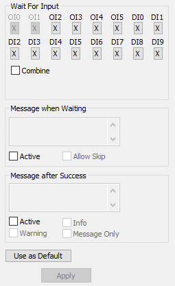
Figure 271: Wait For Input |
Wait For Input: Stops the marking process until the specified input bit(s) of the IO port is set to high or low. ▪X: Do not care / Ignore input bit. ▪0: Wait for corresponding bit state 0. ▪1: Wait for corresponding bit state 1. Combine: Allows to select multiple input bits. All need to be in the selected state to proceed. Message: If the check button Active is selected a message box appears containing the text defined in Message when the specified input bit(s) is(are) high/low. The marking process continues after the message box has been replied to. It is also possible to set no Input, but a message appears. In this case Active and Message Only has to be selected. Additionally an info or warning sign can be added to the message box. The message box only appears, if any text is typed in. Use as Default: Set the current configuration as default. Default name of the control is for current shown state: '5 - H' (masked bit 5, wait for bit high state (H) ) |
|---|
|
Bit position count starts with "1", but corresponds to bit "0" at the hardware! Find Bit to Pin assignment in Global Settings → IO |
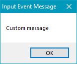
Figure 272: Message Active |
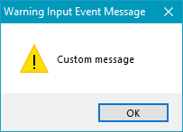
Figure 273: Message Active + Warning |
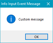
Figure 274: Message Active + Info |