|
<< Click to Display Table of Contents > Position within the system |
  
|
|
<< Click to Display Table of Contents > Position within the system |
|
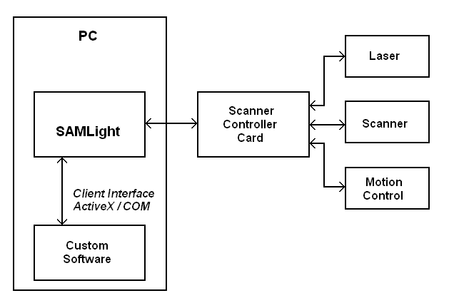
Figure 1: Position within the system
Possible configurations for using SAMLight are:
1. One USC or RTC card with SAMLight:
A single scanner controller card can be included in the system. For SAMLight standard mode simply connect the USC card via USB cable or if using a USC-2 it is also possible to connect via Ethernet. The RTC card has to be fitted in one of the PCI slots of the PC. Configuration of the hardware is explained in chapter "Hardware Settings".
2. One USC-2 card using Flash mode:
Flash mode is only available for USC-2 cards. For the Flash mode the USC-2 doesn't have to be connected to the PC via USB cable but it is necessary to connect it via an RS232 terminal to send ASCII commands to the card or connect via a Telnet Client using an Ethernet connection. However it is not necessary to run SAMLight.
3. Remote control of SAMLight:
It is possible to communicate with SAMLight via the Client Control Interface. The Client Control application can be run inside the same PC or it can be run on a remote PC and then communicate via TCP or plain ASCII commands. The Client Control commands are explained in the chapter Client Control Interface.
4. Using more than one Scanner Controller Card:
It is possible to access more than one scanner controller card at the same time. This feature is called Multi-Head. One can address up to 6 scanner controller cards with SAMLight. Then each of the cards control a unique laser. If using the Head2 feature one scanner controller card can control 2 scan heads using one single laser. The marking of the secondary scan head is the same as for the primary scan head. This mode is also possible with the Flash. If there are more than one USC-2 card, each card can be addressed using for e.g. the visible USC-server. If using the visible USC server with more than one USC-2 card please be careful when using the button InfoView, because it is not always clear which of the cards is used for this button.
5. Using Job IO Selection mode:
The Job IO Selection mode is a kind of half SAMLight plus a half of Remote control. The job that should be marked is issued via the Input pins of the card. These are the Opto_Ins or Digi_Ins of USC cards or the Digital_Ins of RTC cards. This mode can be enabled when SAMLight is already running or it can be enabled while in Flash mode. Detailed description will be given in chapter Mark for SAMLight and chapter Option Flash for the Flash mode.