|
<< Click to Display Table of Contents > Laser |
  
|
|
<< Click to Display Table of Contents > Laser |
|
The following dialog can be reached by using menu item Settings → System → Laser, here the laser and the shutter control can be configured.
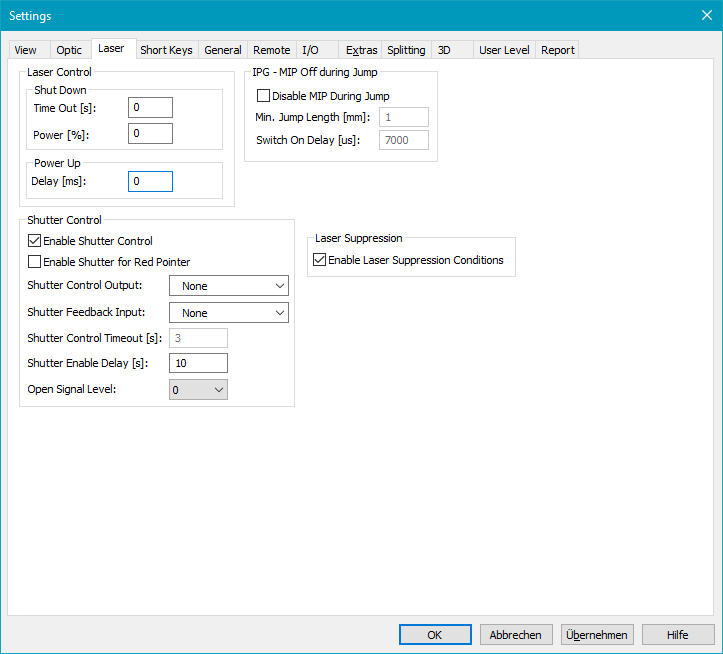
Figure 55: Laser Settings Dialog
Laser Control:
Shut down (power save mode):
Time out [s]: The Laser is going to power save mode after a defined time in which the laser was not active. If a value of 0 is entered here the laser power save mode feature is disabled.
Power [%]: Percentage of laser power for the power save mode. When the power is '0' the laser will shut down.
Power up:
Delay [ms]: When the laser is in power save mode and is going to normal power again a delay can be defined for the power up procedure. In this power up time the laser power will ramp from the power save to full power. The laser gate and the marking in process signal will not be active during the power up procedure. After the power up procedure the laser is in normal mode again and the marking procedure will begin.
IPG - MIP off during jump: This field is available only if using an USC-1 or USC-2 card and if IPG is selected under Settings → System → Optic → Advanced → Mode. If an IPG laser is connected this mode allows it to switch off Emission Enable (connected to OPTO_OUT_0) during jumps.
Disable MIP during jump: If this checkbox is activated then the IPG laser will be switched off during jumps.
Jump Length [mm]: Jumps that are longer than this value will lead to a switch off.
Delay [µs]: When switching on after a jump, this delay is executed before the scanner continues with the next vector.
Shutter Control:
Enable shutter control: Enable the shutter control functionality. All other parameters can be edited
Enable shutter for red pointer: Enable the shutter functionality for activation of the red pointer.
Shutter control output: Specify the output bit that is used to control the shutter can be defined. It sends opening and closing signals to the shutter depending on current state of the application. If the shutter is closed, an opening signal is sent before the laser is turned on e.g. for marking operations. If marking has finished and the enable delay (please see input field described below) has elapsed a close signal is sent to the shutter.
Shutter feedback input: Select a digital input that can be used for reading back the current opening or closing state of the shutter.
Shutter control timeout [s]: Here a timeout value can be configured that is related to the Shutter feedback input. If the shutter is controlled by the application to open or close an error message is displayed and the current operation is cancelled if that operation takes longer than the timeout that is configured here. This timeout requires an input where the current state of the shutter can be read back.
Shutter enable delay [s]: With this delay the shutter can be closed automatically and without any user interaction. If more seconds have been gone after the last time the laser was turned on, the shutter is closed automatically. So this field defines a delay after the last marking operation after that the shutter will be closed.
Open signal level: Change the signal level for the Shutter control output. The user can change between level 0 (active high) and level 1 (active low). With this option the behaviour of the scanner software can be modified in order to fit to the used shutter hardware.
Level 0: Not recommended to use! The Shutter control output signal during the boot process until the first marking procedure might be wrong and the shutter first operates correctly after the first marking.
Level 1: Recommended to use! Depending on the required signal level for the shutter, the selected Shutter control output bit can be inverted manually.
Laser Suppression:
Laser Suppression Condition: Activates the possibility to set conditions for laser suppression for selected entities.