|
<< Click to Display Table of Contents > Optic Settings |
  
|
|
<< Click to Display Table of Contents > Optic Settings |
|
Get this dialog by clicking on Settings at the Hardware Settings dialog. See chapter Setup Tool.
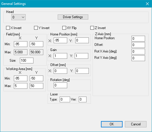
Figure 400: General Settings for Head 0
Select the head with the box at the top. Then define the field and the working area for this head. The values shown in the dialog above define a field with 100 mm size for each head. The total center in the middle of the two fields and an overlapping area of 10 mm in x direction.
The corresponding values for head 1 are shown below:
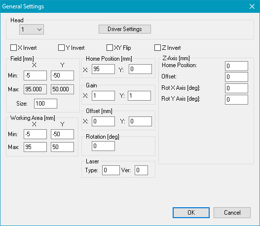
Figure 401: General Settings for Head 1
When the field and the working area have been defined, the driver specific settings have to be defined for each head. Select Head 0 and press button Driver Settings. Here define the specific settings as correction file location, the DLL files etc. for the scanner card. Repeat this step for all installed heads/cards. The optic specific setting can also be changed within the software by selecting Menu bar → Settings → System → Optic.
In the View2D for MultiHeads you will see the resulting working area for both heads.