|
<< Click to Display Table of Contents > Entity Info |
  
|
|
<< Click to Display Table of Contents > Entity Info |
|
The Entity Info property page shows the type and the name of the selected entity.
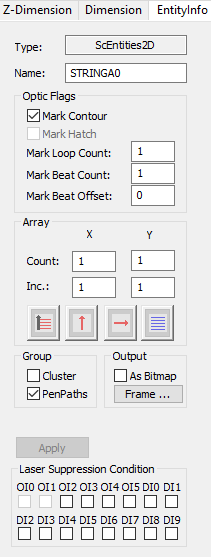
Figure 297: Entity Info Dialog |
Name: Here a name can be set for an entity that can be used to decide what its purpose is within the job, to access it via the Client Control Interface or to reference it from within a serial number. Optic Flags: The markable flags can be changed within this page separately for the contour and for the hatches generated with the hatcher. This flags define whether to mark the entity or not. Mark Loop Count: Defines how often an entity is marked when a mark command is issued. For example, a circle can be marked 100 times with every mark command to form a hole inside a material. If -1 is entered here the entity will be marked infinitely often. Mark Beat Count: Defines after how many subsequent mark commands an entity should be part of the mark. Mark Beat Offset: Allows a shift of the Mark Beat Count for every entity. Array: The array functionality allows to create reference copies of the selected entity in X and Y dimension. Reference copies in Z dimension can be found in the Z-Dimension property page. Count: Define the number of copies in X and Y dimension. Inc.: Define the distance between the copies in X and Y dimension. Laser Suppression Condition: This set of checkboxes allows to define an input pin for the laser suppression. If a signal is applied to the selected pin, the LaserGate is suppressed for this entity. The scan head will move, but without laser ouput. Laser Suppression needs to be activated.
|
|---|
Group:
Cluster: If the entity is a group, it can be clustered. A clustered group will be hatched as one single object while in a unclustered group each entity of groups is hatched separately.
PenPaths: Groups have an assigned pen as well. The pen path of the group is executed when the following two points are true:
•When the group-pen-path is enabled (Group > EntityInfo > PenPaths).
•And when the pen-pen-path is enabled (Group assigned pen number > Paths > Activate) as well.
If the pen path of the group is executed all pens within this group will be ignored! This includes pen paths of sublevel objects as well.
Output As Bitmap: If an entity is selected then by activating this checkbox the entity is transformed to a Bitmap. After that the Bitmap property page becomes available and the bitmap can be modified like a normal bitmap.
Frame...: This button opens an extra dialog to specify a frame of blank pixel (in mm) which are added to the bitmap.
Head ID: Manually assign which scanner head is used to mark this entity in Multihead mode. MultiHeadSplit and Auto Split Mode take only into effect, when it is here 'Auto'.
Assume there are 3 entities inside a job with following settings:
Entity |
Mark Loop Count |
Mark Beat Count |
Mark Beat Offset |
|---|---|---|---|
1 |
1 |
1 |
0 |
2 |
10 |
2 |
0 |
3 |
5 |
3 |
1 |
Table 36: Example for three entities with different mark loop count, mark beat count and mark beat offset
With these settings the following mark sequence can be generated:
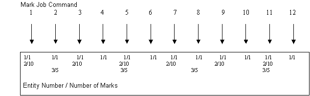
Figure 298: Example for marking order with mark loop count, mark beat count and mark beat offset
•Entity 1 is marked every mark one time (default).
•Entity 2 is marked every second mark and then 10 times.
•Entity 3 is marked every third mark and then 5 times. The Beat Count is offset by 1. So the first time the entity will be marked is on Mark Command 2.