|
<< Click to Display Table of Contents > Scanner and Laser delays |
  
|
|
<< Click to Display Table of Contents > Scanner and Laser delays |
|
The scanner and laser delays are defined in the laser style parameters dialogs. This chapter gives a short explanation of the delay terms.
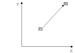
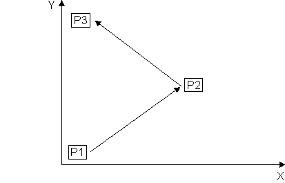
Assume that the XY Mirror system is commanded to go from P1 to P2 in XY-plane with a desired speed v.
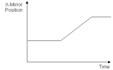
In the following only the X-Mirror is covered, the Y-Mirror is completely analogue.
The move command for the X-Mirror looks as follows:
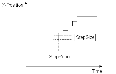
Since the controller card is not able to output values in an arbitrary short time period it has to approximate the desired curve in so called 'microsteps' with a time length of StepPeriod – typically 10 to 50 µs and a position change of StepSize. The requested speed v is the quotient from StepSize/StepPeriod.
Since the X-Scanner with attached mirror is an inert system it can not follow the controller commands in short time but has some time lag.
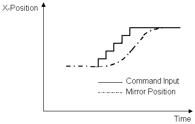
Due to this fact a command input like shown below would lead to the result that the X-Mirror would never reach position P2.
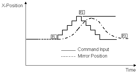
For this reason the controller card inserts a user definable delay between the end of the last vector and the start of the new vector.
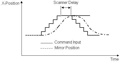
There are 3 kinds of scanner delays:
Delay |
When are the delays used? |
|---|---|
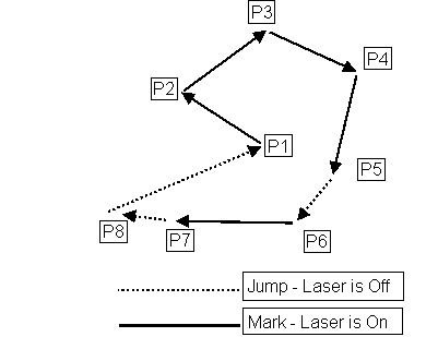
Jump |
Points P1,P6 and P8 in the picture below. |
Mark |
Points P5 and P7 in the picture below. |
Poly |
Points P2,P3 and P4 in the picture below |
Table 74: Example of scanner delays
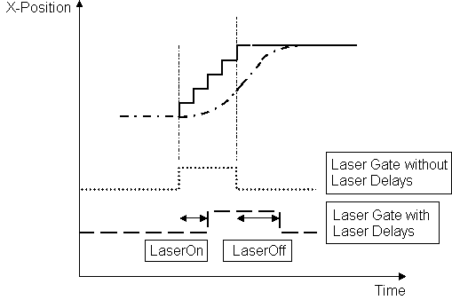
Since the X-Mirror can not accelerate in an arbitrary short time to the requested speed or deaccelerate to zero speed, two additional delays are used to control the delayed switch on and off of the laser gate signal. These are the laser on and the laser off delay.
LaserON delay: Time beginning from the output of the first microstep the controller card waits before it switches on the laser.
LaserOFF delay: Time beginning from the output of the last microstep the controller card waits before it switches off the laser.
Example for laser delays: