|
<< Click to Display Table of Contents > Card Specific: USC-2/3 |
  
|
|
<< Click to Display Table of Contents > Card Specific: USC-2/3 |
|
For the USC-2/3 card, two MOTF channels are available.
•The MOTF signals of Channel 0 (37-pin connector) are single-ended: MOTF_CH0_A and MOTF_CH0_B.
•The MOTF signals of Channel 1 (extension 40-pin connector) are differential: MOTF_CH1_A+, MOTF_CH1_A-, MOTF_CH1_B+ and MOTF_CH1_B-. Do not use this channel single ended!
USC-2/3 |
|---|
single ended tracks: Channel 0 |
37-pin connector: MOTF_CH_0_A |
37-pin connector: MOTF_CH_0_B |
differential tracks: Channel 1 |
40-pin connector: MOTF_CH_1_A+ |
40-pin connector: MOTF_CH_1_A- |
40-pin connector: MOTF_CH_1_B+ |
40-pin connector: MOTF_CH_1_B- |
Table 56: Possible MOTF connections for USC-2/3
Here, the individual options for a USC-2/3 card are described. To get to the dialog window below (figure 353), select Menu bar → Settings → System → Optic → Advanced. Enable Marking On The Fly and then go to Settings.
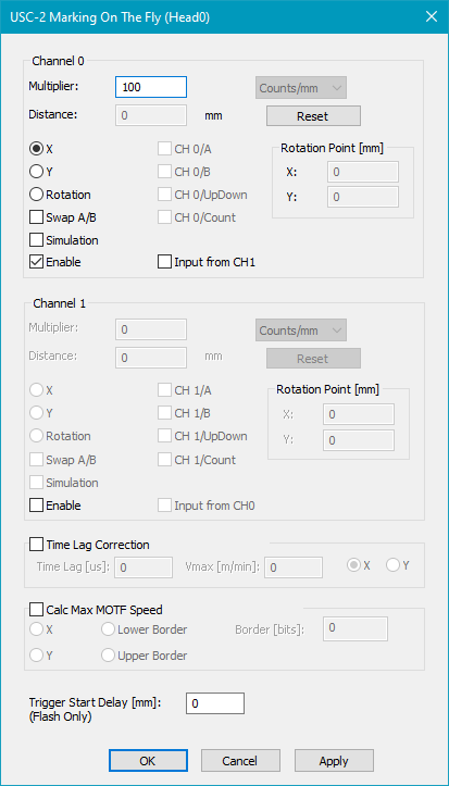
Figure 353: MOTF Settings for USC-2/3 Cards
Channel 0/1: There are two separate channels for MOTF on USC-2/3, Channel 0 and Channel 1.
Enable: Activate this checkbox to enable the desired channel for Marking On The Fly. It is possible to use both (see example rotated scan head).
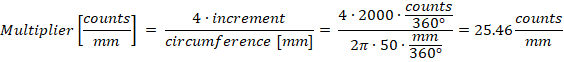
Multiplier: Unit in [Counts/mm]. When using Simulation mode, choose [mm/s] or [m/min] as unit. Using a negative value inverts the direction of the MOTF compensation.
Example of a USC-2/3 MOTF-Multiplier calculation. In this calculation the radius of the encoder wheel is 50 mm and the encoder is generating 2000 pulses per track (A and B) and full rotation:
Distance: If an encoder is used or if simulation is enabled, the distance of the Marking On The Fly movement is shown here. Normally, this number starts to increment as soon as the encoder or simulation mode is activated and when the belt is moving.
Reset: This button resets the distance counter to 0.
X/Y: Choose the axis in which the scanner is moving during Marking On The Fly (for neutral optic settings).
Rotation: A special feature which is only available for a USC-2/3 card is the rotational Marking On The Fly. Therefore activate the radio button Rotation. Then, choose the appropriate units - either Counts/deg or Deg/sec (Deg = Degrees). Finally choose the center of the rotation in Rotation Point. You might want to first center the job in the View2D before setting the center X and Y values.
Swap A/B: If activated, the direction of encoder counting will be inverted. The effect of this checkbox is identical to changing the hardware wiring between track A and track B.
Simulation: Activate this checkbox to enable the Simulation Mode.
Input from CH1/0: When activated, the encoder signals of the other MOTF channel are used for MOTF correction. The state of Swap A/B is also taken form the source channel. See Rotated scan head for an example of application.
Time Lag Correction: To compensate the delay of the scan head, a 'Time Lag [µs]' can be defined. Depending on the current MOTF speed this result in an offset. 'Vmax [m/min] / Time Lag [µs]' is the maximum of this offset. The 'X' and 'Y' radio buttons define the direction of the Time Lag Correction. This feature only works when the encoder pulses result in a positive increase of the distance value. After any changes of the Time Lag Correction, the 'Settings → System → Optic → Advanced → Store' button must be clicked.
Calc Max MOTF Speed: In standalone (flash) mode, it is possible to check the maximal possible MOTF speed of the current job. Steps to use this feature:
•Enable Calc Max MOTF Speed. Only the checkbox must be enabled, the other settings are taken from the MOTF settings above. If both MOTF channels are in use, the CH1 settings are taken.
•Click Settings → System → Optic → Advanced → Store.
•Stop the MOTF belt movement such that there are no more encoder pulses. If the calculation is done while the belt is moving, the result will be less accurate.
•Mark a job in flash mode. Please note that the calculation is only working for jobs without any control objects.
•Start the server in visible mode (<SCAPS>\system\sc_usc_server /v). Select the USC-2/3 card and click on the InfoView button and scroll down to 'MaxMOTFSpeed [m/min]'.
•The 'MaxMOTFSpeed [m/min]' value should be a close approximation of the maximum possible MOTF speed for the current job.
Trigger Start Delay: When a value for the delay is entered, a ScMotfOffset and a ScWaitForTrigger object will be added to the top of the job list. These control objects will delay the job execution until the distance[mm] is reached after the external trigger signal. There must be only one trigger pulse and this pulse must be shorter than the "Distance[mm] / MOTF-Speed[mm/s]". This feature is only implemented for standalone mode (flash mode).
Only the following configurations allow correct compensation and advanced MOTF features (like ScMotfOffset or endless loop applications):
Setup |
USC-2/3 MOTF settings |
|||
|---|---|---|---|---|
MOTF direction |
Phase shift track A - B |
Orientation of MOTF coordinate |
Sign of MOTF multiplier |
Swap A/B checkbox |
→ or ↑ |
B after A |
normal |
positive |
unchecked |
→ or ↑ |
B after A |
inverted |
negative |
unchecked |
→ or ↑ |
B before A |
normal |
negative |
checked |
→ or ↑ |
B before A |
inverted |
positive |
checked |
← or ↓ |
B after A |
normal |
negative |
unchecked |
← or ↓ |
B after A |
inverted |
positive |
unchecked |
← or ↓ |
B before A |
normal |
positive |
checked |
← or ↓ |
B before A |
inverted |
negative |
checked |
Table 57: USC-2/3 MOTF settings for different setups
Phase shift track A - B (refer to chapter Encoder Signals):
•B after A: track B is 90° (pi/2) phase-delayed to track A (of the corresponding channel).
•B before A: track B is -90° (-pi/2) phase-delayed to track A (of the corresponding channel).
Orientation of MOTF coordinate:
•normal: the MOTF axis is not inverted in SAMLight → Settings → System → Optic
•inverted: the MOTF axis is inverted in SAMLight → Settings → System → Optic
The orientation of the coordinate system of the UCF correction file has no influence on the MOTF settings.
It is highly recommended to set 'Settings → System → Optic → Rotation' to '0'.
•The rotation rotates the entity, but not the MOTF direction.
If a rotation is required, implement the rotation directly in the UCF correction file.
Do not forget to press the 'Store' button and save the settings.
In 'sc_usc_server → Info View', the following should be true if MOTF is set up correctly:
•MotfCNT counts positive when 'sign of MOTF multiplier' is positive. MotfCNT counts negative when 'sign of MOTF multiplier' is negative.
•MotfCNTS counts always positive.
•MotfSpeed is always positive.
|
If the marking is started with an external trigger (sensor), it is recommended to start the marking in trigger mode (Mark →Trigger) to avoid jitter of the position. |
|---|
