|
<< Click to Display Table of Contents > Card Specific: USC-1 |
  
|
|
<< Click to Display Table of Contents > Card Specific: USC-1 |
|
For the USC-1 card, there is one channel available: the single ended MOTF_CH_0 channel of the 37 pin connector:
USC-1 |
|---|
single ended tracks: Channel 0 |
37-pin connector: MOTF_CH_0_A |
37-pin connector: MOTF_CH_0_B |
Table 54: Required MOTF connection for USC-1
Here, the individual options for a USC-1 card are described. To get to the dialog window below (figure 352), select Menu bar → Settings → System → Optic → Advanced.
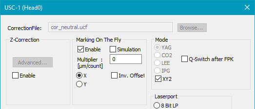
Figure 352: MOTF Settings for USC-1 Cards
Marking On The Fly:
Enable: Activate this checkbox to enable Marking On The Fly.
Simulation: Activate this checkbox to enable Simulation Mode.
Multiplier [µm/count]: Enter the value of the multiplier here in µm/count. If you enter a negative value, the MOTF compensation is switching the direction.
Example of a USC-1 MOTF-Multiplier calculation. In this calculation the radius of the encoder wheel is 50 mm and the encoder is generating 2000 pulses per track (A and B) and full rotation:
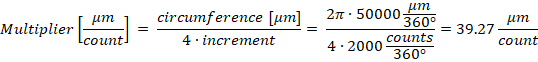
X/Y: Choose the direction in which the target is moving during Marking On The Fly (for neutral optic settings).
inv. Offset: ScMotfOffset control objects can only be positive. It is possible that the MOTF compensation is set up correctly but the MOTF counter value is decreasing (counting negative). In this case, you have to enable this checkbox to be able to use ScMotfOffset control objects.
|
|
|---|
Only the following configurations allow correct compensation and advanced MOTF features (like ScMotfOffset):
Setup |
USC-1 MOTF settings |
|||
|---|---|---|---|---|
MOTF direction |
Phase shift track A - B |
Orientation of MOTF coordinate |
Sign of MOTF multiplier |
Inv. Offset checkbox |
→ or ↑ |
B after A |
normal |
positive |
unchecked |
→ or ↑ |
B after A |
inverted |
negative |
checked |
→ or ↑ |
B before A |
normal |
negative |
unchecked |
→ or ↑ |
B before A |
inverted |
positive |
checked |
← or ↓ |
B after A |
normal |
negative |
checked |
← or ↓ |
B after A |
inverted |
positive |
unchecked |
← or ↓ |
B before A |
normal |
positive |
checked |
← or ↓ |
B before A |
inverted |
negative |
unchecked |
Table 55: USC-1 MOTF settings for different setups
Phase shift track A - B (refer to chapter Encoder Signals):
•B after A: track B is 90° (pi/2) phase-shifted to track A.
•B before A: track B is -90° (-pi/2) phase-shifted to track A.
Orientation of MOTF coordinate:
•normal: the MOTF axis is not inverted in SAMLight → Settings → System → Optic
•inverted: the MOTF axis is inverted in SAMLight → Settings → System → Optic
The orientation of the coordinate system of the UCF correction file has no influence on the MOTF settings.
It is highly recommended to set 'Settings → System → Optic → Rotation' to '0':
•The rotation rotates the entity, but not the MOTF direction.
If a rotation is required, implement the rotation directly in the UCF correction file.
|
•If the marking is started with an external trigger (sensor), it is recommended to start the marking in trigger mode (Mark →Trigger) to avoid jitter of the position. •ScMotfOffset control objects do not work in MOTF simulation mode for USC-1 cards. |
|---|
