|
<< Click to Display Table of Contents > Analog In Toolbar |
  
|
|
<< Click to Display Table of Contents > Analog In Toolbar |
|
![]()
Figure 175: Analog In toolbar
The Analog In toolbar is available only if USC-2/-3 is used. It can be configured for the two 10 bit analog inputs (values from 0-1023) of USC-2/-3 card. The input signals must be connected to Ana_In_Ch_0 or Ana_In_Ch_1 in respect to Ana_In_GND. The current bit value of the analog input bit can be checked at sc_usc_server.exe in visible mode at InfoView.
|
The input voltage should not exceed 10.3 V. |
|---|
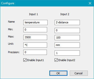
Figure 176: Analog In dialog
Input 1: Settings for analog input ANA_CH_0.
Input 2: Settings for analog input ANA_CH_1.
Name: Here a name can be set for the Analog Input bit that can be used to decide what its purpose.
Min: Here the minimum of the unit range have to be set for the Analog Input bit, which should corresponds to a digital value of 0 or 0 V.
Max: Here the maximum of the unit range have to be set for the Analog Input bit, which should corresponds to a digital value of 1023 or about 10.3 V.
Unit: Here the physical unit of the Analog Input bit can be set.
Precision: Here the number of decimal places can be set. Please keep in mind that the displayed numerical resolution is limited to (Max value - Min value) / 1024.
Enable Input1: Activates the display of analog input ANA_CH_0.
Enable Input2: Activates the display of analog input ANA_CH_1.
If activated the Analog In toolbar displays the converted voltage according to settings of Analog In dialog in accordance with the set names and units there.
