|
<< Click to Display Table of Contents > Analog In |
  
|
|
<< Click to Display Table of Contents > Analog In |
|
|
Any input voltage will be live updated and can influence the running marking procedure. |
|---|
|
This feature is only supported for USC-2/-3 cards. Z offset is only available for USC-3. |
|---|
This dialog offers the possibility to set an offset of scanner position in x, y and z direction by putting a voltage on analog input.
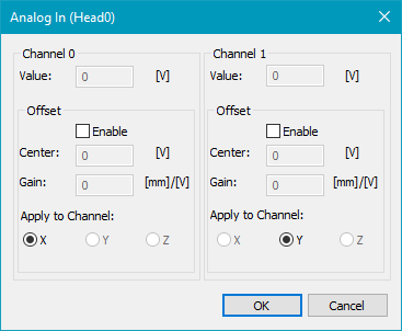
Figure 23: Analog-In Dialog
Value: Value shows the voltage value been placed on pin Analog In.
Center: In this checkbox you can define a voltage value with which the Offset is 0 mm.
Gain: In this checkbox you define the width of offset per Volt. Positive and negative values are valid. Depending on the sign, the direction of the offset is adapted.
Example: set Center = 5 V, Gain = 2 mm/V for Offset X, when you place 6 V on pin AI 0, the scanner gets an offset of 2 mm in x direction. For Center = 5 V, Gain = - 2 mm/V, the scanner gets an offset of - 2 mm in x direction when you place 6 V on pin AI 0.
|
Up to 2048 bit, the offset is set immediately. For values > 2048, an overflow occurs to protect the scan head. If an overflow occurred, the scan head moves very slowly to the new position. |
|---|

