|
<< Click to Display Table of Contents > GND |
  
|
|
<< Click to Display Table of Contents > GND |
|
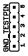
Figure 17: GND
The "GND_TESTPIN" is only needed to connect the ground terminal of your oscilloscope probe to avoid noisy signals. Table 12 shows the pin assignment of the "GND_TESTPIN".
Pin |
Signal |
Description |
|---|---|---|
1 |
GND |
Ground all over the DB-37, also connected to the USC-1 GND and machine GND. |
2 |
LASER GND |
When using laser signals in opto-insulated mode, this is the GND of the external power supply. (See the USC-1 manual for further information.) |
3 |
USC OPTO GND |
Normally this signal is GND except when supplying the Opto I/Os externally. (See chapter 2.2.3 of the USC-1 manual for further information.) |
4 |
LASER GND TEST |
Depending on the operating mode you choose the signal is GND or LASER GND. (See chapter 3.6 for further information.) |
5 |
OPTO GND |
This is the opto-insulated GND to the machine. |
Table 12: GND pin assignment