|
<< Click to Display Table of Contents > Tilt Compensation (USC-3 only) |
  
|
|
<< Click to Display Table of Contents > Tilt Compensation (USC-3 only) |
|
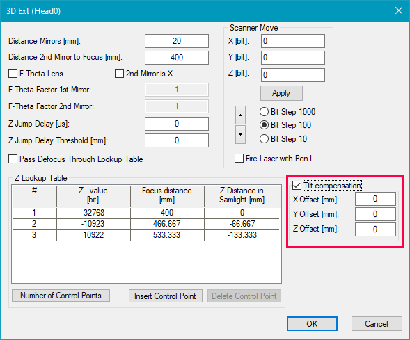
As is can be possible that the scan head is not 100% perpendicular to the marking area, minor corrections can be done via the Tilt Compensation. This step should be done before the Z Lookup Table Calibration, if needed, but a temporary lookup table is necessary at least.
The Tilt Compensation is currently only possible for Optical Settings with no XY flip, no inverts, no rotations, and no gains. Flips, inverts and rotations can be integrated into the correction file if needed.
Figure 88: Tilt Compensation Parameters |
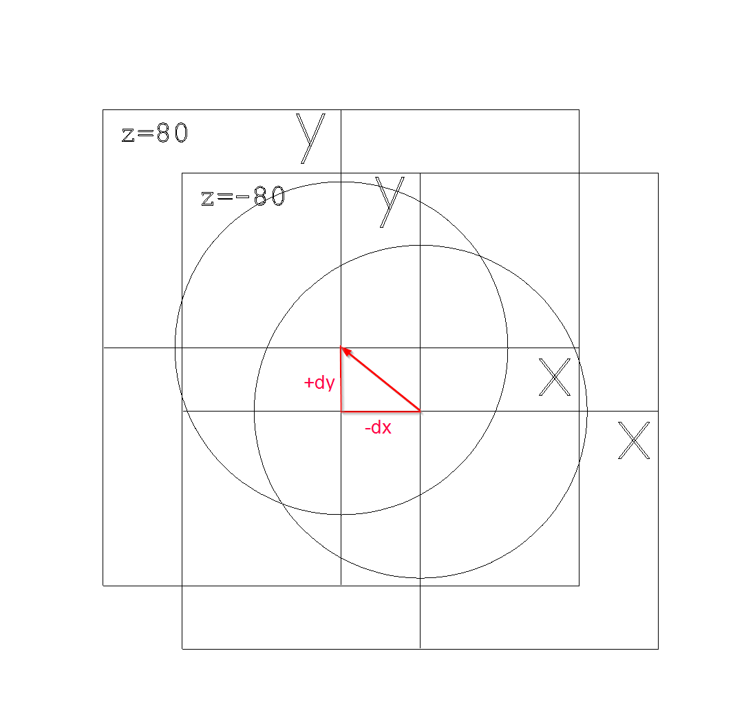
In order to determine the offset parameters, mark a cross at X=0 and Y=0 at two distinctly different z-heights. If the scan head is slightly tilted, a difference dx and dy can be measured (see image below). The marking at the longer focus distance is the reference. These measurements are the x- and y-offset parameters (please mind the sign). The z-offset is the difference between the z-heights and is always positive and >0. The correction is applied with OK.
Figure 89: Tilt Compensation Measurement |
|
Before using the Tilt Compensation, please make sure to adjust the scan head mechanically as best as possible, as the Tilt Compensation does restrict the working area. The smaller the Tilt Compensation via software, the smaller the loss of working area. |
|---|