|
<< Click to Display Table of Contents > General Settings |
  
|
|
<< Click to Display Table of Contents > General Settings |
|
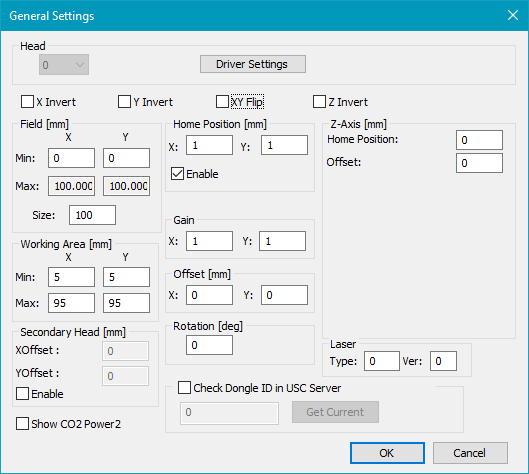
Figure 20: General Settings Dialog
Head: Choose the Head for which the driver settings should be edited. The drop down menu is only enabled if the HeadCount is greater than 1.
Driver Settings: Opens the Driver Settings dialog where you can adjust hardware specific settings.
Invert: Each scanner axis can be inverted separately.
Flip: The X and the Y axis can be flipped, so that the X axis gets the Y coordinates and vice versa.
Field [mm]: The size of the field has to be typed in mm.
Min: This value can be negative, so that the field can be set up symmetrically to the origin.
Max: This value is computed as Min + Size.
Size: The edge length is Size. The field is always a square. Specifies the maximum scanning field. This is the maximum field the scanner system can drive. In general it depends on the optical system (like lenses, etc.), the scanning distance and the maximum scanning angle of the scanner system. On 16 bit scanning systems the field extent corresponds in general to the bit values -32767 to 32767 respectively.
If the dimensions of output do not correspond to the dimensions of the drawn object, this can be corrected by changing the field size. After decreasing the field size, the marked objects will be larger. Increasing the field size will reduce the size of the marked objects. The new field size is being calculated out of the current field size in the following way:
corrected field size = current field size * C / O
C is the current output dimension and O is the original dimension of the drawn object.
Working Area [mm]: The Working Area has a rectangular shape. The area is defined by Min and Max. The Working Area has to be within the Field. Consider rotation too.
Secondary Head [mm]: Enables an X and Y Offset for the secondary head when using the Head2 license.
Show CO2 Power2: Feature for USC-1 only: Activates the ability to select a second power value in the pen settings when using CO2 lasers.
Home Position [mm]: If HomeJump is enabled, the scanner goes back to this position after marking. Please see home jump pen for further information.
Gain: The X and Y gain values are thought to compensate slightly X, Y gain errors to archive a quadratic field. Values less than 1 will reduce the size of the marked objects. Values greater than 1 will increase the size of the marked objects. Global gain errors which have the same deviation in X and Y directions should be corrected by changing the size of the scanner field (see above).
Example for calculating the size of the scanner field:
If for example the correction table has a step size of 550 bits/mm and the scanner has a 16 bit scanning system, the
size of the scanner field = 65535 bits * mm / 550 bits = 119.16 mm
Considering a Gain factor:
scanner field in x direction = 119.16 mm * Gain X
scanner field in y direction = 119.16 mm * Gain Y
Please find further information regarding the gain under backgrounds.
Offset [mm]: With the offset values you can slightly compensate X/Y offset errors to achieve the theoretical midpoint of the scanner field. Global offset errors which have the same deviation in X and Y direction should be corrected by changing the Field parameters.
Rotation [deg]: The scanner output will be rotated counter clockwise by this angle.
Check Dongle ID in USC Server: Checks whether the specified Dongle ID is connected to the system. The check is executed when starting SAMLight and will compare the IDs entered for each head with the respective position in the USC-server.
Laser: Type in Type and Ver as advised by SCAPS.
Z-Axis [mm]: This option is only for Optic3D. Please note: for successful z-position setting, the Z Dimension min and max must be set and enabled in SAMLight - settings - system - optic.
Z Home Position [mm]: If HomeJump is enabled, the scanner goes back to this position after marking.
Z Offset [mm]: Adds an offset to all Z values.
USC cards: XY coordinates are not compensated, like Pen Defocus.
RTC cards: XY coordinates are compensated, unlike Pen Defocus.