|
<< Click to Display Table of Contents > Series resistor |
  
|
|
<< Click to Display Table of Contents > Series resistor |
|
Threshold level of Opto_In and Digital_In.
In general, TTL level is specified with a low level between 0V and 0.8V and a high level between 2.0V and 5.0V.
If the maximum voltage is then increased to 24V, these thresholds do not change automatically. In order to change the thresholds, series resistors need to be introduced.
Figure 56 shows the threshold levels for maximum voltage of 5V (TTL) in part a, part b shows the same thresholds but with increased maximum level of 24V and part c shows the change of the threshold for high level which is increased to U_Th by the introduction of a series resistor R_ext.
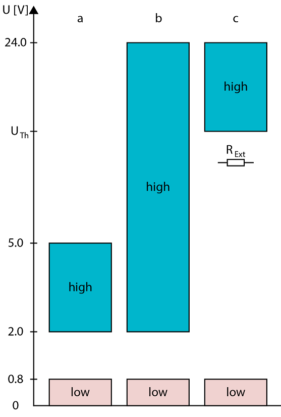
Figure 56: Levels of TTL logic and their manipulation for higher maximum voltage
Case a: A voltage up to 5V is given to an Opto_In or Digital_In. Gap between 0.8V (low) and 2.0V (high).
Case b: A voltage up to 24V is given to an Opto_In or Digital_In. Gap between 0.8V (low) and 2.0V (high).
Case c: A voltage up to 24V is given to an Opto_In or Digital_In. Gap between 0.8V (low) and (high). The corresponding resistor can be calculated via:
Opto_In:
Table 57 gives the internal parameters of the opto_inputs for USC cards.
USC |
U_PH |
I_PH |
R_INT |
|---|---|---|---|
USC-1 |
ca. 1V |
340 uA |
4k7 |
USC-2 |
ca. 1V |
440 uA |
3k3 |
USC-3 |
ca. 1V |
360 uA |
3k3 |
Table 57: Internal parameters of Opto_Inputs for USC cards
Digi_In:
Table 58 gives the internal parameters of the digital_inputs for USC cards
USC |
U_IC |
I_IH |
R_INT |
|---|---|---|---|
USC-2 |
ca. 1.7V |
14 uA |
15k |
USC-3 |
ca. 1.7V |
17 uA |
15k |
Table 58: Internal parameters of Digi_Inputs for USC cards